

I stopped by Home Depot and picked up some Schedule 40 PVC pipe, Tees, elbows, a piece of 1 3/8" steel punched flat bar and a box of 1/2" self tapping screws, a couple 1/4" x 2 1/4" Hex Head Cap screws and nuts and some 1/4" washers. I created a decent AP stand for under $20.
The stand is light weight, easy to disassemble for transport and worked great. The customer has used them at several events now and they have worked perfectly. I finally got around to modeling the stand in Solidworks 2010 and have created a Bill of Materials and some drawings saved as PDF files.
Not shown in the BoM or model files are 1x1in. UV Mounting Base Model # HW-4ACB SKU #296167. These are small pieces of plastic with slots for cable ties. I screwed them into the PCV pipe, put cable ties in a loop and then ran the Ethernet cable through them. They keep the Ethernet cable organized. I have considered drill holes in the elbow near the mounting strap and running the cable internally. I think it would look better but it would make assembly at the site more involved.

Tools Required
Hack sawDisk sander
Vise
Hand drill with a 1/4" and 3/32" drill bit
Sand paper
If you have access to a band saw so much the better! First cut the pipe into the following:
(1) piece 9" long
(4) pieces 15 3/4" long
(4) pieces 3" long
(2) pieces 48" long
Use the disk sander to square up the edges and the sand paper to smooth out the edges. If you don't have a disc sander you can purchase a PVC cutter for around $15. This will cut the pipe square enough to use as is.
Cut the 1 3/8" steel 5" long and round the corners on the disk sander. If you don't have a disc sander use the sand paper to remove the burrs and use as is. It will still work just fine.
Drill 1/4" holes through the 9" piece of pipe using the SCH40-1-25x9.pdf file for dimensions. The link to the files is at the end of the blog.
Assembly
Assemble the 9" pipe and 1 3/8" steel mount using the AP-Mounting-Assy.pdf as a guide. When complete it will look like this: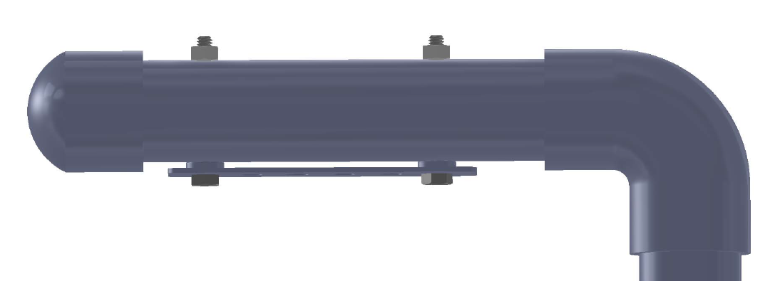
The Cisco AP mount fits perfectly on the 1 3/8" strap and the PVC keeps it from sliding off.
Assembling the base
This step is easier with two people.
Start with a Tee and insert a 3" piece of pipe into each side. The 48" section will go into the third.
Attach a Tee to each 3" section.
Insert one 15 3/4" piece of pipe into each Tee.
Insert a 3" piece of pipe int each Tee.
Attach a 45 degree fitting to each 3" piece.
Insert one 15 3/4" piece of pipe into each 45 degree fitting.
Place caps onto each 15 3/4" piece of pipe.
Insert a 48" piece of pipe into the vertical Tee.
Place a 20" long 3/4" x 2 1/2" piece of wood under the center Tee. Rotate each 15 3/4" pieces down until the caps are on the floor. You can leave the base flat but this creates a more stable base than leaving the base flat.

Make sure that the 48" pipe is vertical or slightly forward.
Drill 3/32" holes through each Tee and 3" piece of pipe.
Screw the #8 self tapping screws into the holes.
Drill 3/32" holes through each 45 degree fitting and 3" piece of pipe.
Screw the #8 self tapping screws into the holes.
Drill 3/32" holes through each 45 degree fitting and 15 3/4" piece of pipe.
Screw the #8 self tapping screws into the holes.
Now you just insert the 48" pipe, attach the coupler, insert the 2nd 48" pipe and attach the elbow with the AP mount. To transport simply remove the AP mount, remove the two 48" pipes and the 15 3/4 pipes.
Here are the Solidworks files, PDF and JPGs of the project. There is a file called ap-stand.wrl in the directory. This is a VRML file. VRML is a format that allows 3d models to be displayed in a browser. You need to install a browser plugin from cortona 3d viewer to view the file.
AP Stand files

This is exactly what I needed! Your content is always so informative and well-researched. Know more about wireless access points.
ReplyDeleteLipo Technology Private Limited offers UV Nylon Cable Tie, designed for high durability and resistance to harsh outdoor conditions. Made from premium UV-stabilized nylon, these ties prevent degradation from sunlight, ensuring long-lasting performance. Ideal for electrical, automotive, and industrial use, our cable ties provide secure bundling. Choose us for reliable, high-quality solutions.
ReplyDelete